This is a tensile test to judge layer bonding/strength of 3d printed parts (FDM).
Wanted to evaluate the z-strength of functional 3d parts, printed with ddPrint.
As we know, a FDM printed part is weaker in Z-direction than in the XY-directions. Good layer bonding means good Z-strength.
Layer bonding is (mainly) affected by two aspects: hotend temperature and a controlled amount of extruded plastic (no voids). DDPrint assists with both of them, through automatic temperature control and controlled extrusion.
To prove the Z-strength, this relative strength test was developed. Instead to measure and compare the absolute strength in XY- and Z-direction, this test compares them directly.
Then the result of this test is the ratio of XY-strength to Z-strength:
relative-strength rs is:

        Z-strength
  rs = -------------       # with 0 < rs < 1.0
        XY-strength
Contents
How it works
As usual for a tensile test, 3d printed test specimens are pulled apart, but we don't measure absolute forces when parts break. Instead, we pull at the XY-specimen and th Z-specimen at the same time and check which one breaks first.
As the name implies, the XY-specimen are printed in XY-directoion and the Z-specimen are printed in Z-direction.
To be able to make an statement about the relative strength, the strength of the Z-specimen (its cross-sectional area) is kept constant. Then we use a series of XY-specimens with increasing strength and test them one-by-one against the Z-specimen.
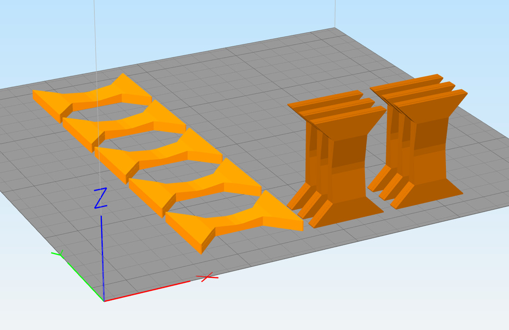
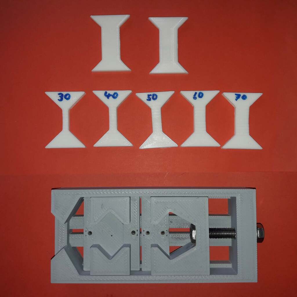
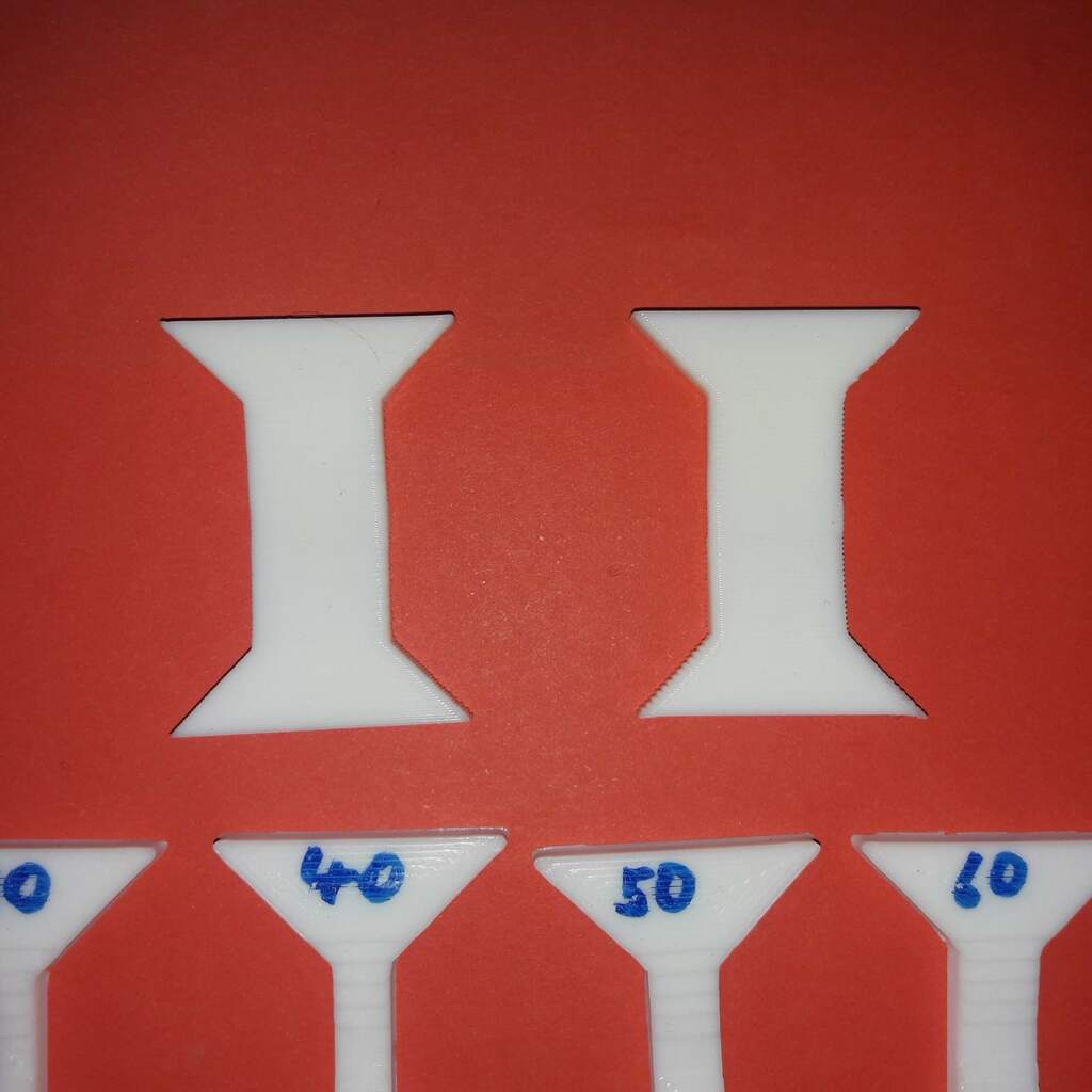
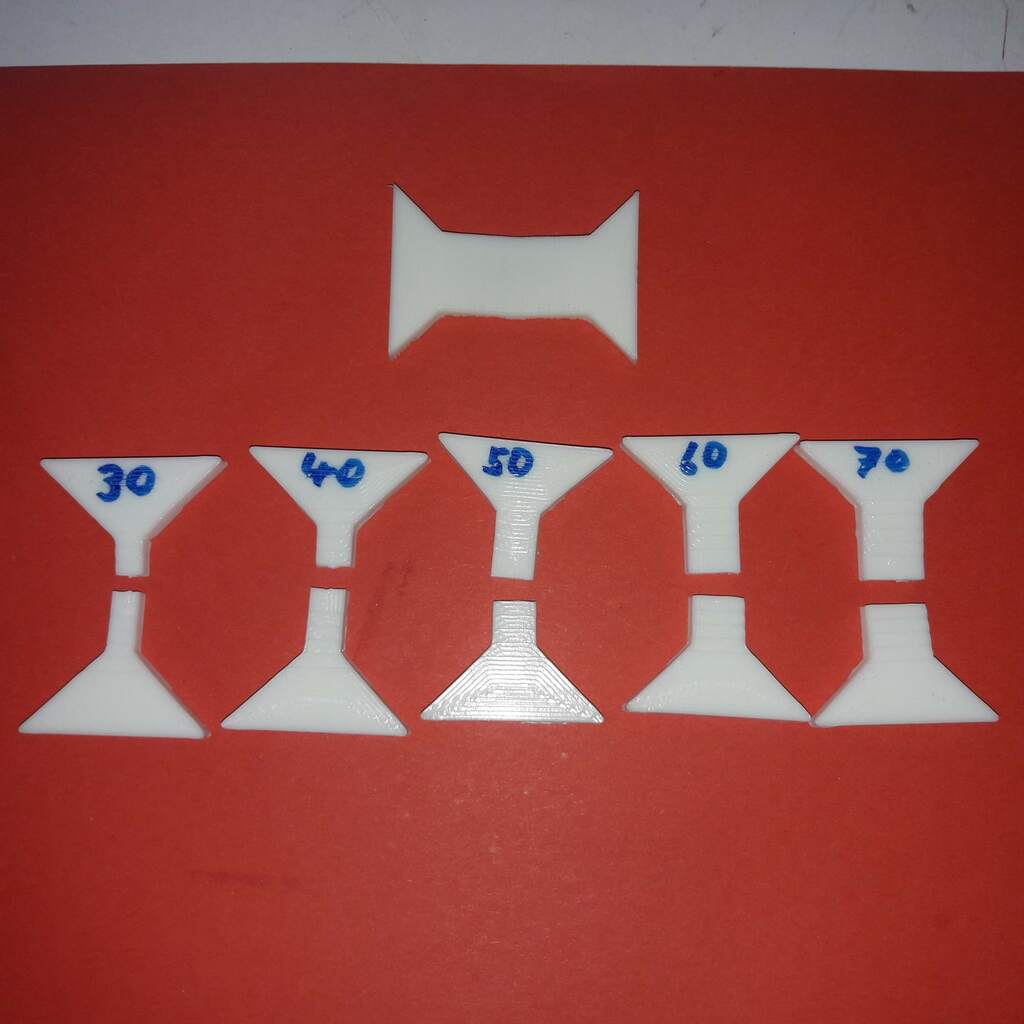
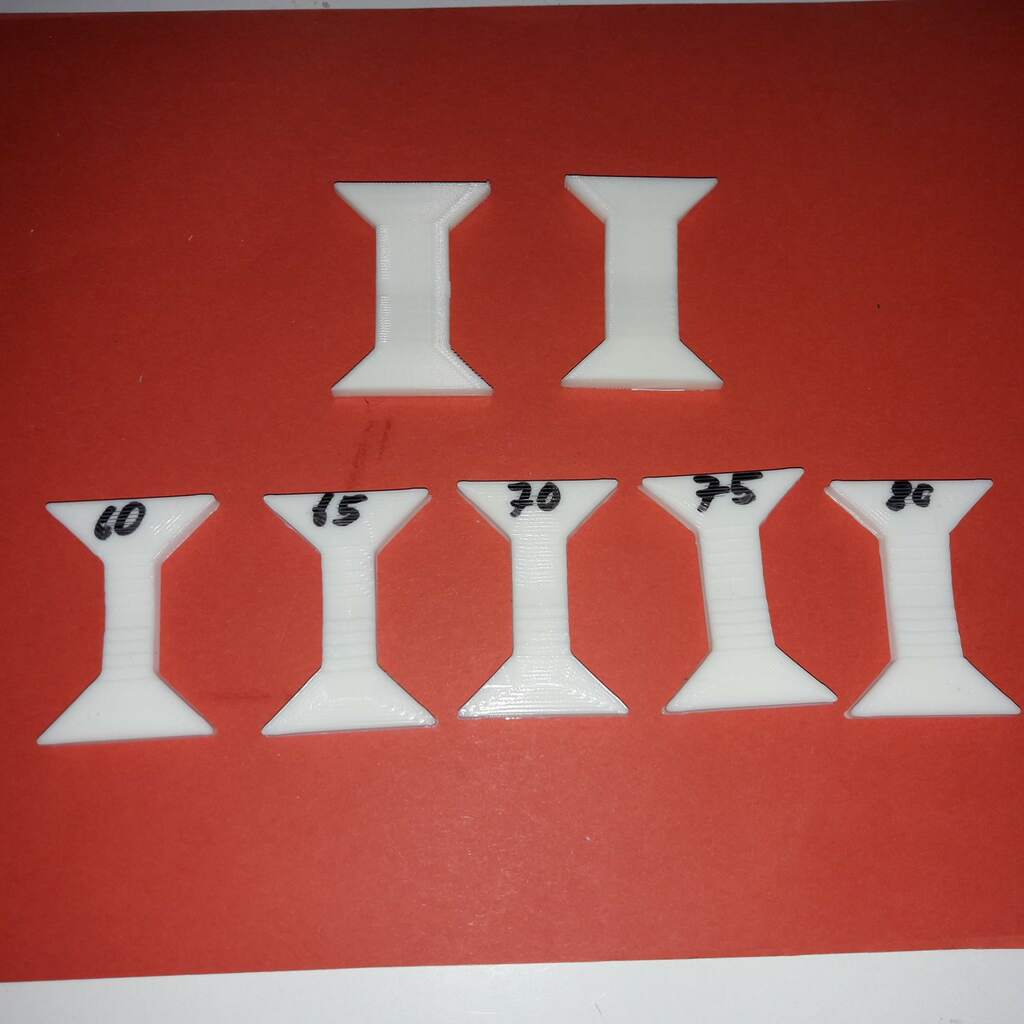
See the following example, the two parts at the top are the Z-specimen. They are printed in Z-direction and have a cross-sectional area of 100%. In the second row, the XY-specimen are shown with increasing stenght/cross-section from 30% up to 70%.
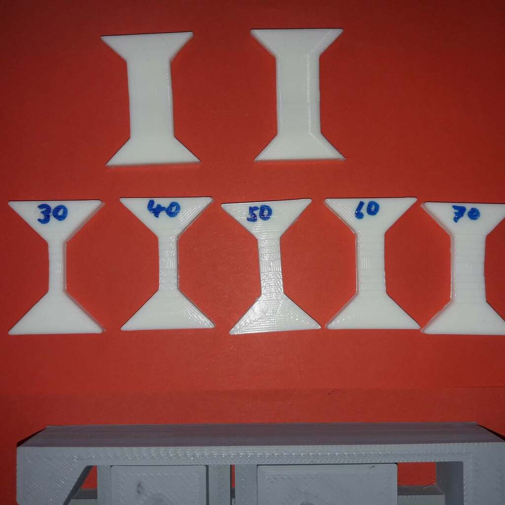
When doing a test run, we start with the weakest XY-specimen, the 30% part in this case. If the Z-specimen is not to bad, the XY-part will break:
We then continue testing the remaining XY-parts until the Z-part breaks. If this happens, we have a approximate measure of the relative Z-strenght:
with
   rs:     relative-strength
   S_XY_0: last XY-strength that did not break the Z-Part
   S_XY_1: current XY-strength that DID break the Z-Part

S_XY_0 < rs < S_XY_1
See below for full examples.
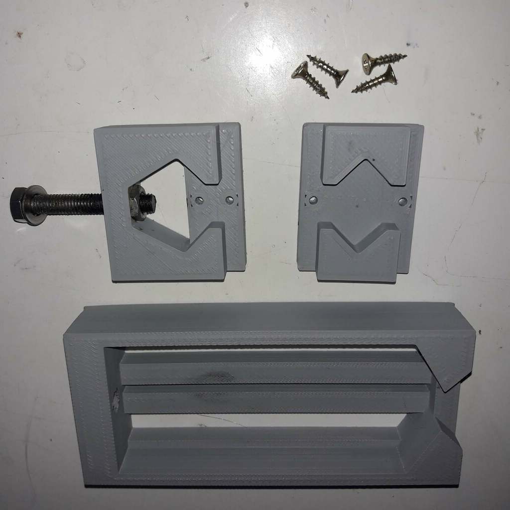
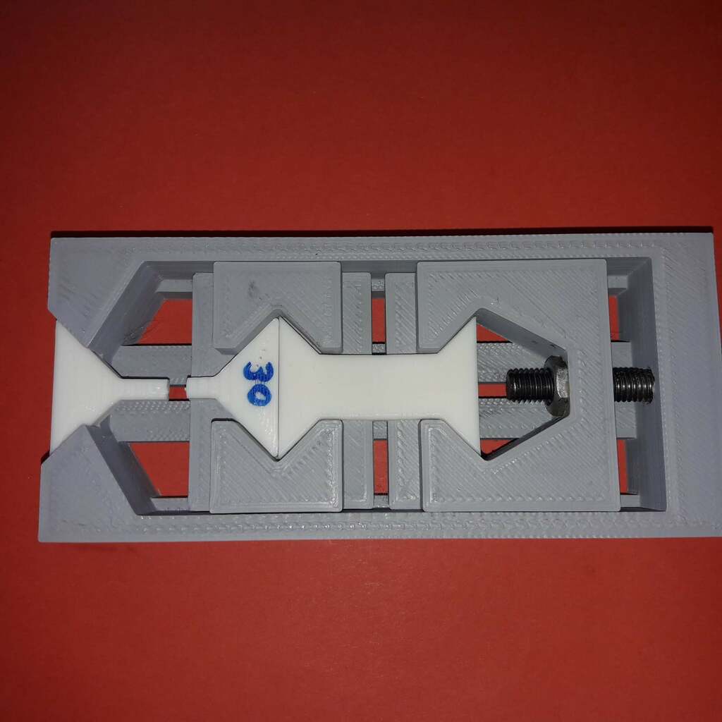
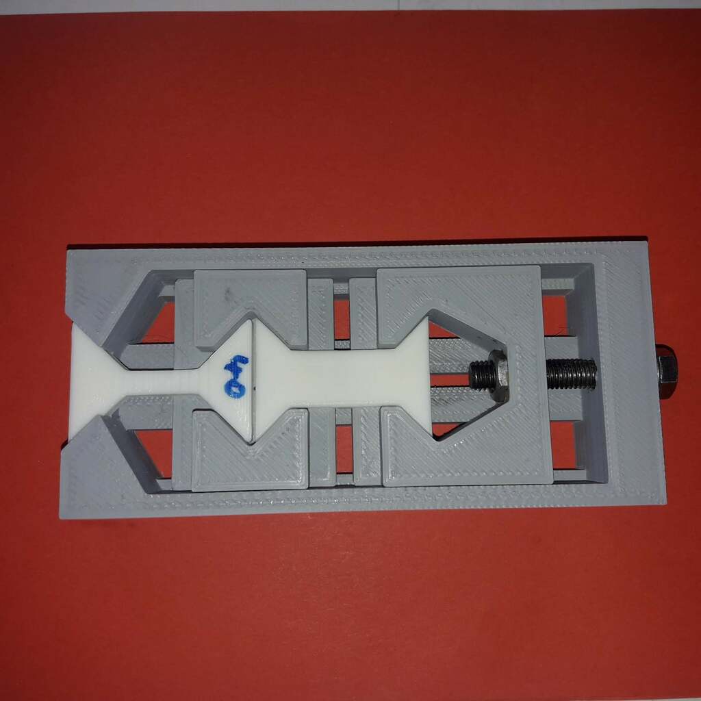
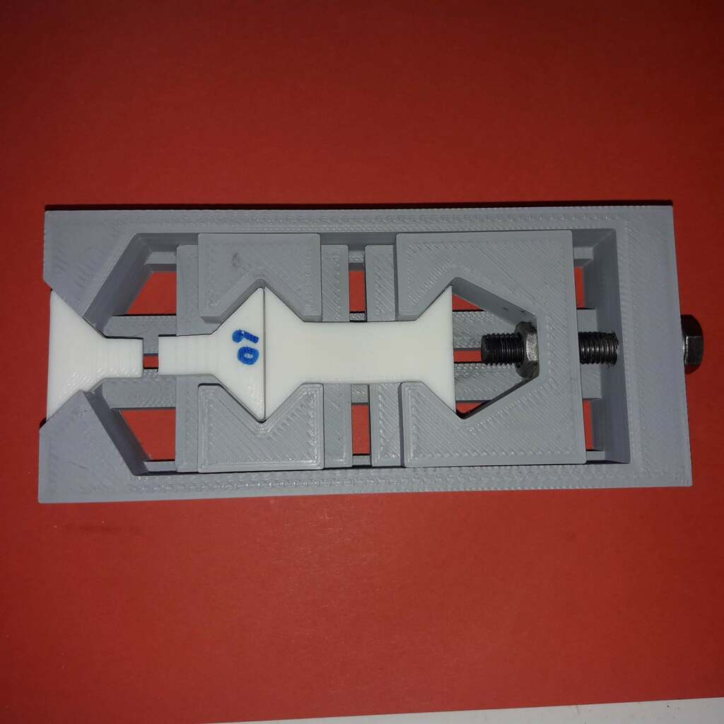
Test device
This is the test device that was designed to do the relative tensile strength test. Printed on the Ender5 ddPrinter with cheap "AW-3D" grey filament.
It consists of a base frame, two sleds and some screws.
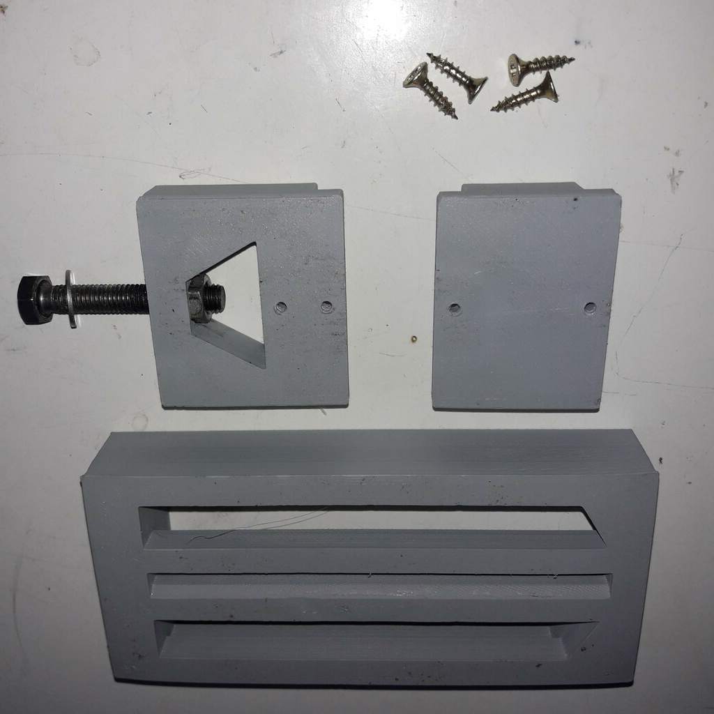
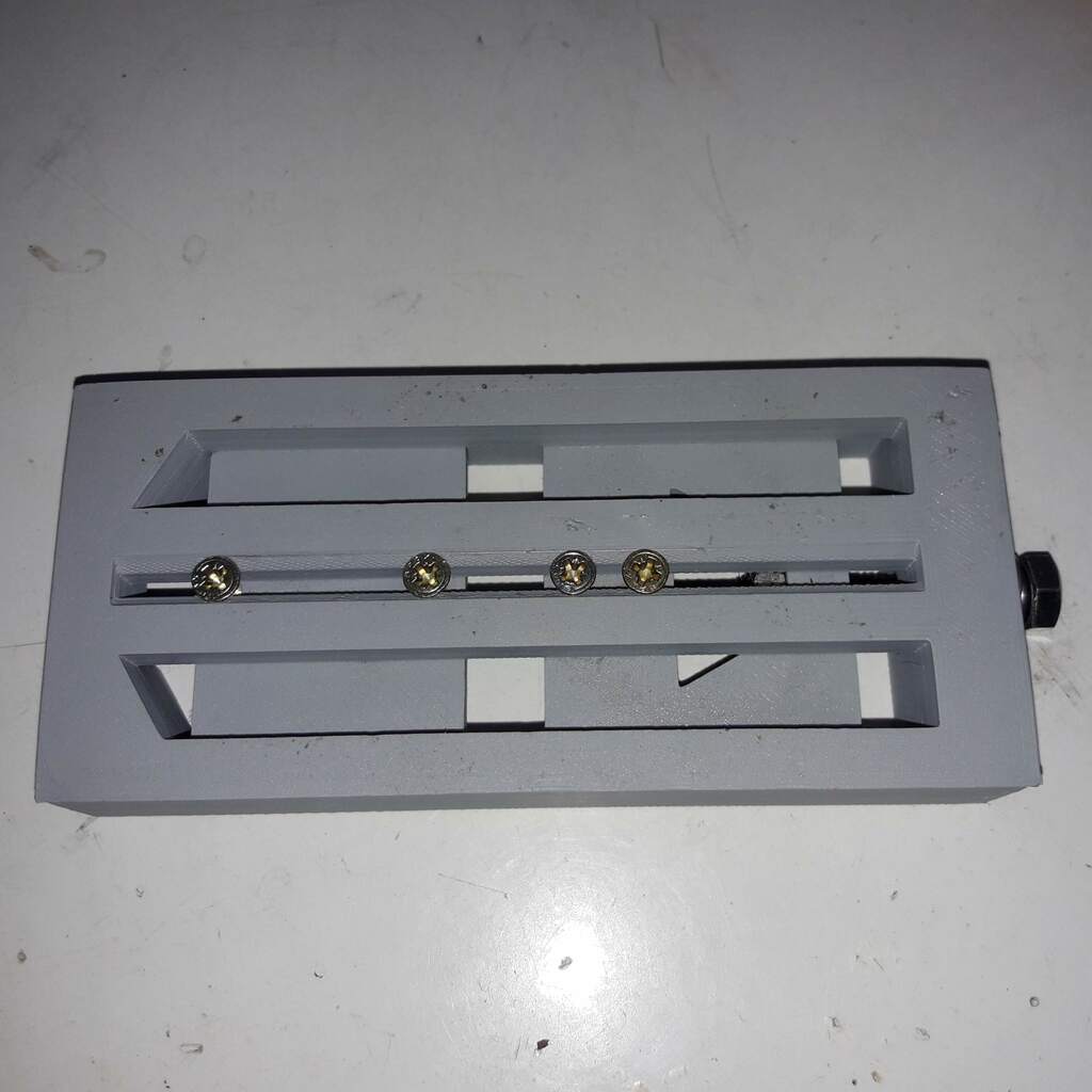

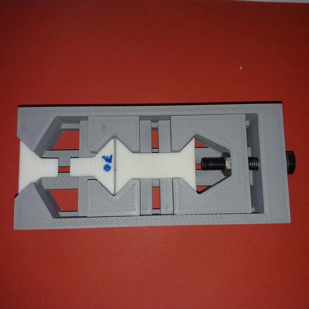
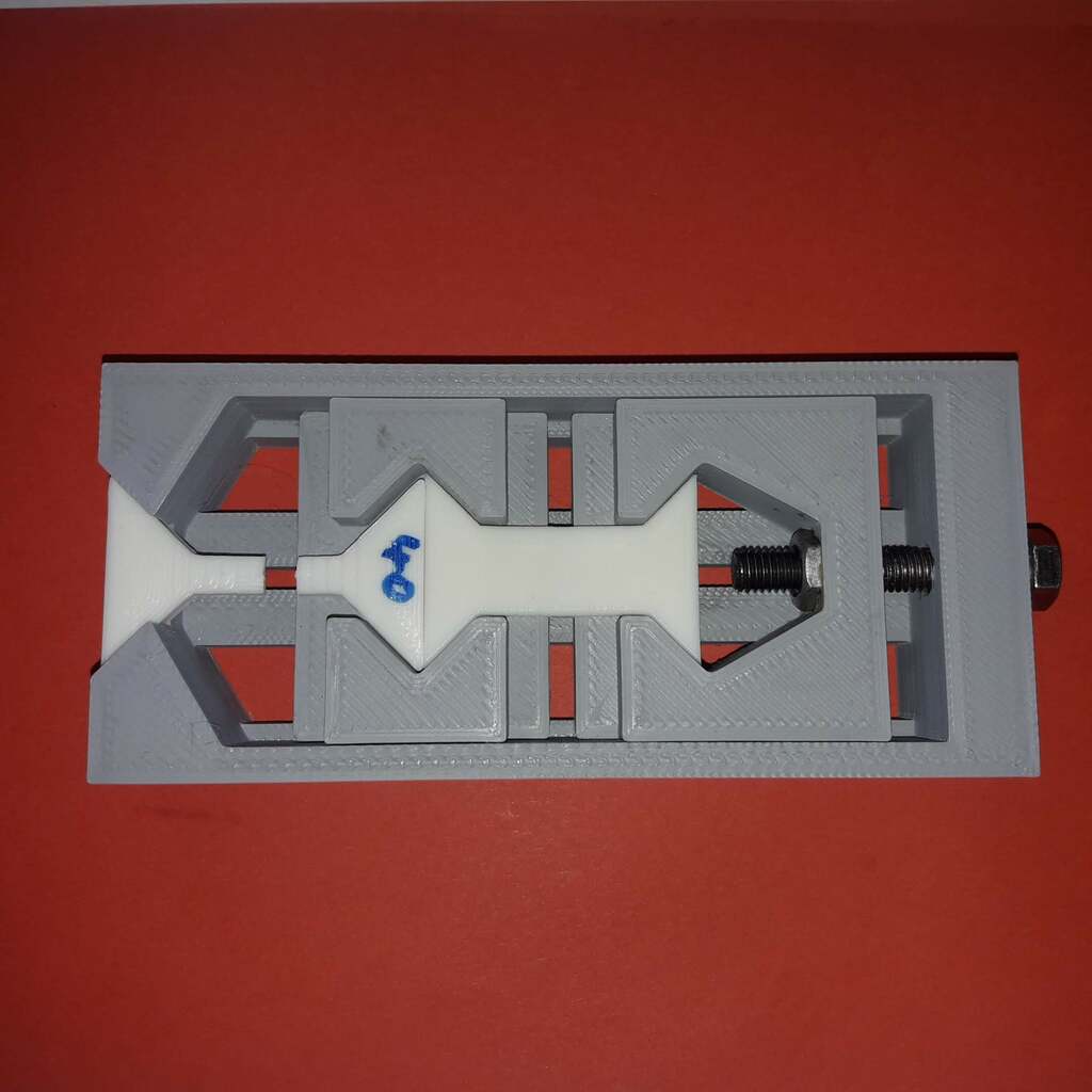
One sled moves freely and its task is to connect the two specimens. The second sled creates the tensile test force using a M8 screw and nut:
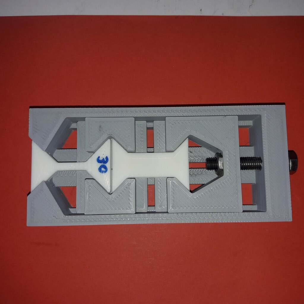
Running a test is simple: insert the XY- and Z-specimen into the testdevice and turn the tension screw until one of the specimen breaks. For safety, use some cloth/towel to cover the testparts to avoid plastic pieces flying around. Safety glasses are in order.
Test specimen
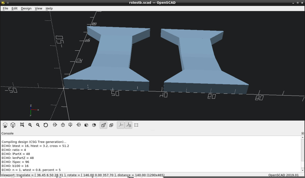
STL files of the specimen are generated using a parametric openscad model.
Dimensions of the Z-specimen is fixed, it has a cross sectional area (in the middle) of
area = width * height
area = 16mm * 3.2mm = 51.2mm²
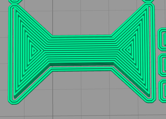
Care has been taken to make the width a whole multiple of the layer width (0.8mm nozzle). The height is a whole multiple of the layerheight (0.32mm) and of the layer width. The reasons for this:
- This gives us a simple sliced object consisting of full strands only, no "single extrusion-fill" or "gap-fill".
- Strength of XY-part can be controlled by manipulation of the width of it (adding/removing strands).
- Z-part is printed vertically/rotated, so the height becomes the depth of the part (3.2mm height is 4 times layerwidth of 0.8mm).
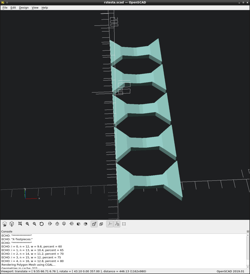
The XY-parts are created using a parametric openscad module, its input is a list that defines the number of parts and the widths (and therefore the cross sectional area) of them to create.
The width is specified in "number of strains", a 100% full width specimen would be 20 strains wide (16mm for a 0.8mm nozzle). One strain equals 5% width/strength.
Following openscad snippet creates five XY-specimen with 60, 65, 70, 75 and 80% strength:
echo("*************");
echo("X-Testpieces:");
echo("*************");

w = [12, 13, 14, 15, 16]; // # widths for 60, 65, 70, 75 and 80% strength

for (i = [0:1:len(w)-1]) {

   echo(i=i, n=w[i], w=w[i]*lw, percent=w[i]*lw*100/b);
   translate([0, i*(bges+3)])
      rotate([0, 0, 90])
            rstesta(w[i]);
   }
The slicer used is Simplify3D, main slicing parameters are:
- 0.8mm nozzle, 0.8mm linewidth
- 0.32mm layers
- 50mm/s speed (resulting vol. flowrate: 12.8mm³/s)
- no bottom or top layers, no infill, everything is printed as outline/perimeter
- no minimum layer time, no slowdown
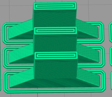
To keep the layer printing time above some threshold and to avoid overheating, the number of Z-specimen is set to six. We don't need them all for testing, but sometimes it's nice to have them for additional tests.
Test runs
The specimens of the following tests were all printed on a Ultimaker 2 ddPrinter (todo: link). Filament used was "Kaisertech PLA White", sliced with Simplify3D using the slicer parameters noted above.
First test run
This test run served to determine the range the relative strength lies in. Assuming the Z-strength is about half the strength in XY-direction, five XY-specimen with a cross section of 30, 40, 50, 60 and 70% were printed. The Z-parts have 100% cross section area.
Printed with default ddPrint parameters (workingPoint 0.5), resulting in the following AutoTemp temperature profile:
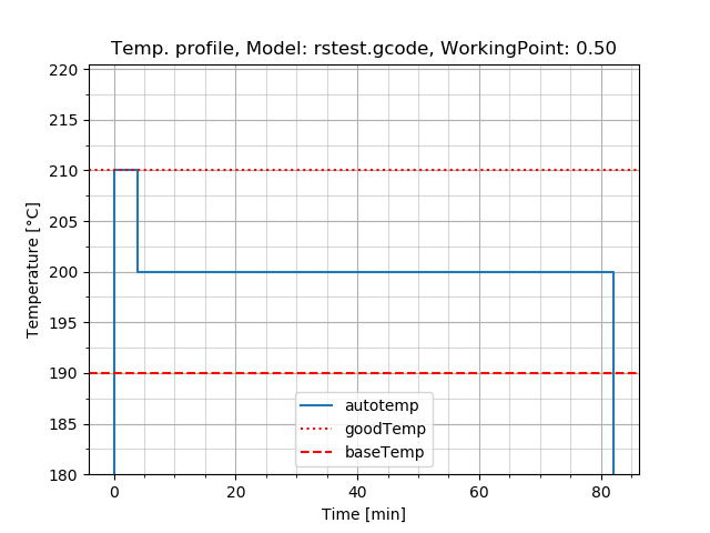
As we can see, ddPrint choosed a Printing temperature of 200 °C and the first layer was printed 10 °C hotter.
Specimen for the first test:
First combination tested: 30% XY-specimen together with 100% Z-specimen:
As we can see, the XY-piece broke. Therefore relative Z-strength is at least 0.3 or 30%. Continue testing the remaining XY-specimen with increasing strength:
All XY-specimen broke, that means relative Z-strength is at least 70%. The initial estimation of a 50% Z-strength was too pessimistic. We have to increase the XY-strength for the next test runs.
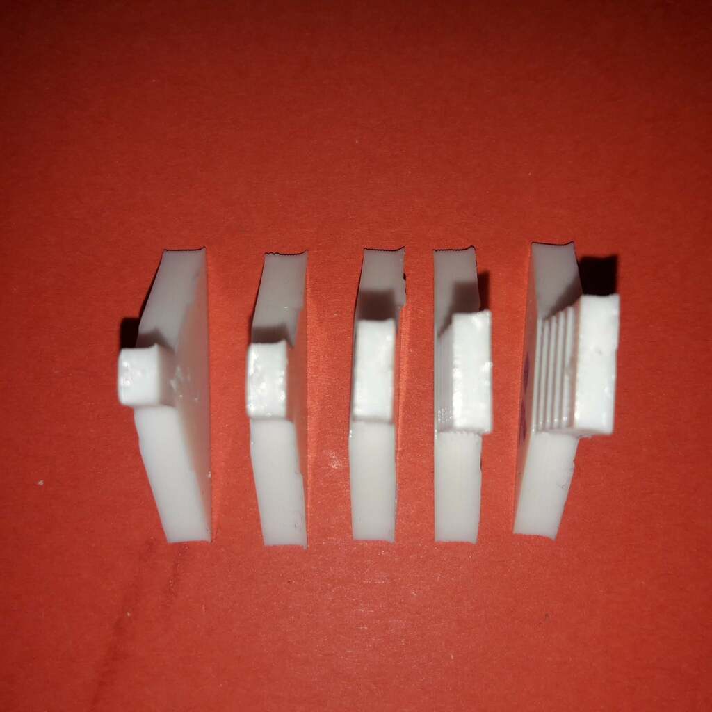
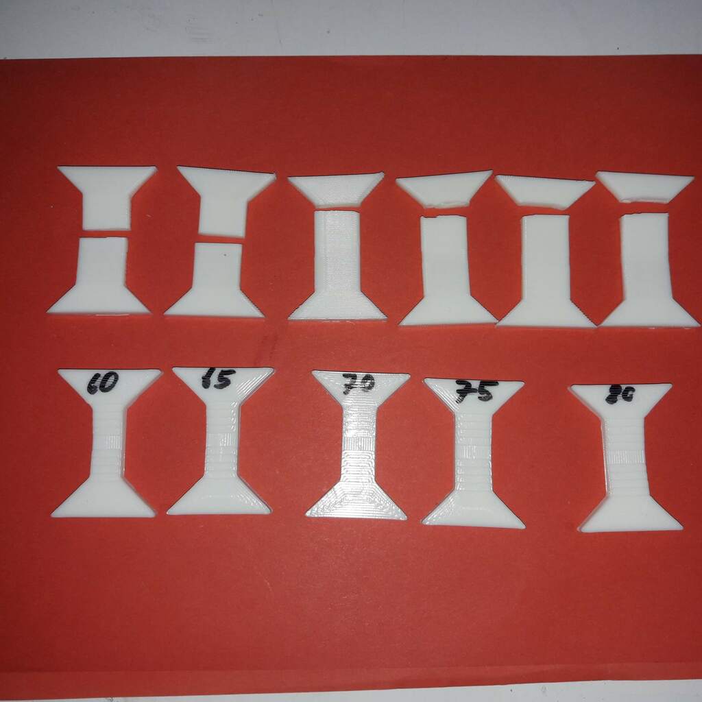
Pictures of the test parts after the first test run and the surfaces of the broken XY-specimen:
Second test run
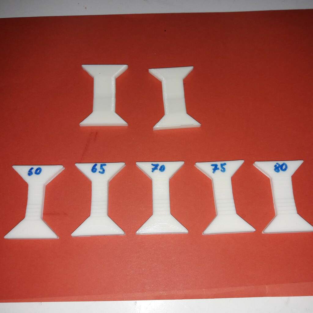
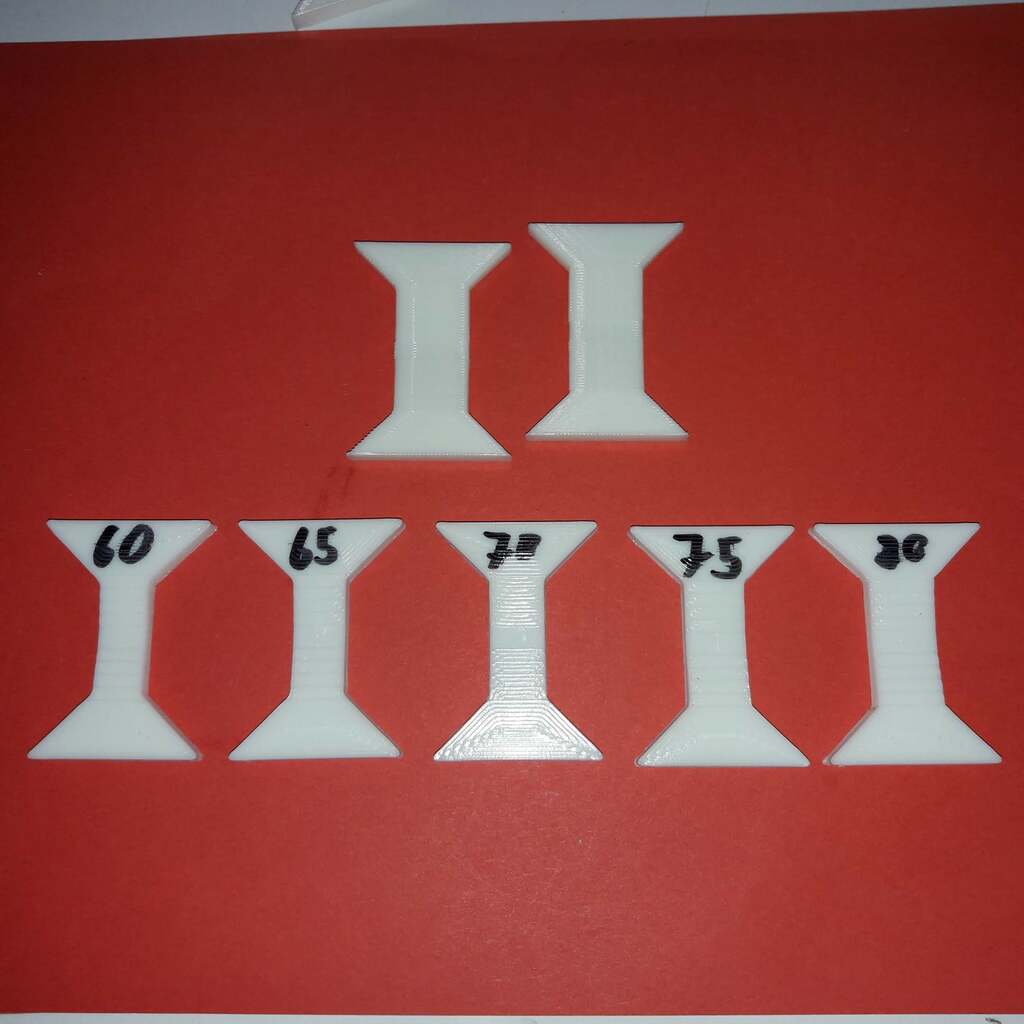
The first run showed that Z-strength is at least 70% of XY-strength. So the strength of the XY-specimen for this test were centered around 70% strength (60, 65, 70, 75 and 80%):
Results are shown in this picture:
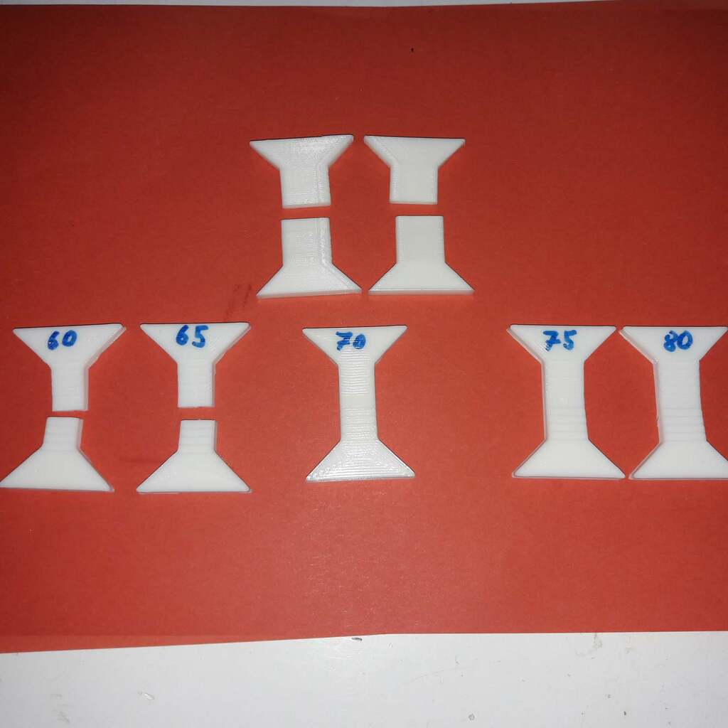
We can see that the XY-specimen up to 65% broke and that the 70% XY-specimen was able to break two of the (100%) Z-specimens. That means, the relative strength for this test is in the range of 65% to 70%. A bit weaker than in the first run but it lies within the scope of the standard fluctuations of FDM 3d printing, i think.
As a result so far: ddPrint creates parts with a relative strength of about 70% using its default settings - a good value as far as i can see.
Playing with the ddPrint working point parameter
The temperatures used by the ddPrint AutoTemp feature can be controlled by the so called "WorkingPoint parameter" (given on the ddPrint command line). The working point (or operating point) is a numerical value in the range between 0.0 and 1.0. Lower values are giving hotter temperature profiles and vice-versa. The default working point setting is 0.5 (used for the tests above).
For more info about the ddPrint working point parameter, see here.
To evaluate the influence the working point/temperature range has on the strength of the parts, two more test runs were done. One with a working point value of 0.25 (hotter) and one with working point 0.75 (colder).
WP=0.25
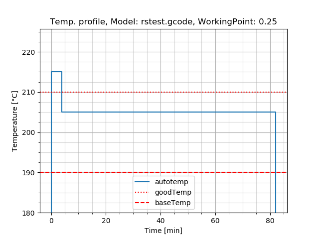
The same specimen as in the second test were printed, but this time using a ddPrint working point value of 0.25. This gives us a higher autoTemp temperature range, in this case a printing temperature of 205 °C (5 °C hotter):
The specimen for this test:
Results:
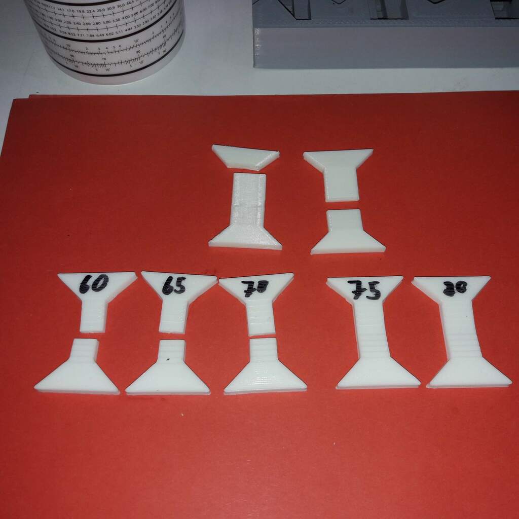
The XY-specimen up to 70% strength broke and the 75% XY-specimen was able to break two of the Z-specimen.
Increasing the printing temperature by 5 °C did not create significant stronger parts, rather a tendency for stronger parts. Layer bonding/Z-strength is in the same ballpark as in the previos tests, relative strength is in the range of 70 to 75%. That means parts created with the default ddPrint settings are already relatively strong.
A test with even higher printing temperatures (wp=0.0, t=210 °C) would be interesting...
WP=0.75
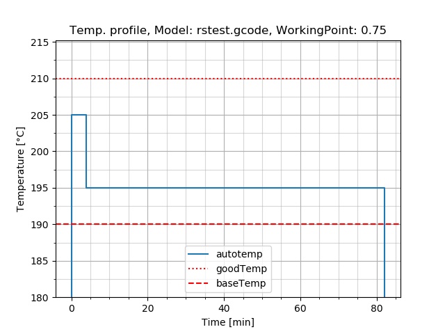
Again the same specimen as in the second test were printed, but this time using a ddPrint working point value of 0.75. This gives us a lower autoTemp temperature range, in this case a printing temperature of 195 °C (5 °C colder):
The specimen for this test:
Results:
This is surprising, lowering the printing temperature by 5 °C (from 200 °C to 195 °C) did create significant weaker layer bonding. The 60% XY-specimen was able to break all the Z-specimen. Relative strength is in the range below 60%.
To determine where the relative strength is located in this case, one could do another test (for example with parts centered around 50% relative strength as in the first test). But i will skip this because i'm interested in stron parts...
Results
To summarise this:
- This test procedure seems to give reasonable and consistent results.
- Relative layer strength in the range of 70% is achieved.
- ddPrint creates strong parts even with its default settings.
- Printing with 205 °C instead of 200 °C does not create significant stronger parts, but there is a tendency for it.
- Printing with 195 °C instead of 200 °C creates significant weaker parts, 200 °C printing temperature seems to be the sweet spot for this filament.
Closing
Suggestions and questions are welcome, direct them to 'erwin.rieger@ibrieger.de' please.